-
Three Maps, One Gear Stick
In the last post I said the MEG’s internal state used to be a locked box, and that once you can reach into it safely the list of what becomes possible gets very long. This is the first thing off that list, and it’s the one I’ve wanted since I started tuning these cars.
Multi-map switching. Three different tunes in the one ECU, selected from the driver’s seat using the gear stick, with the gear display on the dash showing you which map you’re on.
It works. I’ve got it running in the car.
Why bother?
Anyone who’s had a tune done knows the compromise. A map that’s great on a track day isn’t always what you want in traffic, and a map that’s perfect for the daily commute leaves something on the table when you want to have fun. Normally you pick one and live with it, or you pull the ECU and reflash it every time you change your mind.
With multi-map you don’t have to choose. You could have a mild map, the full tune, and a third for whatever suits you, all living in the one ECU and swapped in a few seconds without a laptop in sight.
None of this is new (on other ECUs)
Same as last time, I want to give credit where it’s due. Map switching on Bosch ECUs is well established. People in the diesel world have been doing it on the EDC15 for years, and there are commercial products for the newer Bosch platforms that do it very nicely, saving your chosen map and locking out changes while you’re driving. I looked hard at how they all do it before I wrote a line of my own.
But none of it exists for the MEG1.1. Different chip, different memory layout, different everything. So as usual, the ideas are borrowed and the work is from scratch.
The trick Bosch left behind
Here’s the bit I really like about this one.
Bosch built the MEG1.1 to run more than one car. The same ECU went into the Fortwo and the Roadster in different power outputs, and rather than build a different ECU for each one, Bosch put several complete calibrations into the one FLASH. There are three full calibration blocks in there. When the ECU boots, it looks at the coding in the EEPROM (the same coding I wrote about in the EEPROM post) and picks which block to run for that car. After that, the other two just sit there doing nothing for the life of the car.
So the room for three maps was already there. Bosch built the house with three bedrooms and only ever let you use one. The job was to work out how the ECU picks its block, and then teach it to pick a different one on command, while it’s running.
That turned out to be the hard part.
What it’s like to use
From the driver’s side it’s simple:
- Sitting still, lever in D, hold + for three seconds. The gear display changes from your gear to a number, 1, 2 or 3. That’s the map you’re currently on.
- Tap + or – to step through the maps. Nothing changes yet, you’re just choosing.
- Hold + for three seconds again to confirm. The new map goes live, the number stays up for a moment so you know it took, and the display goes back to showing your gear.
- Walk away mid-selection and after ten seconds it quietly cancels without changing anything.
No switches to fit, no wiring, no extra hardware. It uses the gear stick and dash that are already in the car.
Reading the gear stick
To make that work I had to understand the gear stick at a level the MEG never shows you.
It turns out the lever isn’t a smooth sensor at all. It’s a little bank of switches, and each position (R, N, D, + and -) closes a different pair of them. The MEG reads those switches, cleans them up, and decodes the pattern into what you asked for. Tracing that path through the disassembly told me exactly which pattern means +, which means -, and, just as importantly, which patterns I must never touch. I actually had + and – backwards in my first attempt, and one of my early candidate patterns turned out to be neutral. That’s the sort of mistake you want to make on the bench and not on the road.
The other job was making sure a “hold” and a “tap” can never be confused. Taps are only counted when you let go, and a press held past the threshold isn’t a tap. So the long hold that confirms your map can’t also step you on to the next one.
Talking to the dash
The dash display was a nice surprise. The instrument cluster doesn’t work out what gear you’re in, it just draws whatever character the MEG tells it to over the CAN bus. So a small routine sits in the path of that message and, only while you’re selecting a map, swaps the gear character for a map number. The rest of the time it leaves the factory message completely alone.
That’s the CAN work from the last post paying off again. Once you know which message carries what, and you can write your own code into the path, the dash becomes a display you can use.
The part that took the longest
Getting it to switch at all wasn’t the end of it. The first version looked like it worked. Pick map 2, confirm, and the car was on map 2. Except not all of it was.
The ECU doesn’t run as one program in a loop. It’s lots of separate tasks running at different rates, some every millisecond, some every ten, and one big background loop that ticks away whenever there’s time spare. Most of those tasks look up which calibration block they should be using every time they run, so they followed the switch straight away. The background loop didn’t. It set itself up once at startup and never looked again, so it quietly kept reading from the old map. Hundreds of values, including some that my tunes actually change.
Nothing in the disassembly tells you that. There’s no comment saying “this part never checks again”. I only found it by mapping out every task the ECU runs and following every path the code can take, then asking which parts could still see the old block after a switch. The fix was small once I knew. Finding it was not.
There’s a related catch that no clever code can get around. A small number of values (forty-odd in my files) are only read once, while the ECU is starting up, and then kept. A change to those only takes effect at the next key-on. Commercial map switches on other Bosch ECUs have exactly the same limitation, and my tool now checks for it and warns me if the maps differ in any of those values, so there are no surprises.
Safety first
I’ll say this plainly because it matters. Changing the tune on a running engine is not something to do casually.
- Map changes are only accepted while the car is stationary. Try it while moving and it refuses. That check reads the same speed signal the ECU already uses for its own decisions.
- Every map in the ECU is a complete, validated tune, with its own checksums sorted. There’s no half-finished state it can switch into.
- If the ECU is ever unsure about the stored choice, it falls back to the car’s normal coded map.
- There’s an escape hatch. Hold – while you turn the key on and the car starts on its factory map, whatever was selected before.
And everything has been tested on my own car and on the bench first. I don’t put anything on a customer’s car that hasn’t been through that.
Remembering your choice
The last piece is remembering which map you chose, so it’s still on that map the next time you start the car. The MEG already writes things like clutch and gearbox learning to its EEPROM when you switch off, so the natural place to keep your choice is right alongside them, written during that same shutdown.
Getting that right took a proper deep review of how the ECU starts up and how it looks after its EEPROM, because this is the kind of feature that’s easy to get almost right. That work is done and it’s on the bench now. I’ll confirm it here once it’s proven, not before.
What’s next
I built a tool to go with this, so a map switch can be installed onto a tune cleanly, checked, and removed again if needed, with everything verified before a single byte is written. It already handles both the normal Roadster and Fortwo software and the Brabus software. The Brabus version still needs its turn on the bench before I’ll call it done.
Launch control is still in the “in progress” column. It’s getting closer, and a lot of what I learnt doing this map switch feeds straight into it.
As always
This is bespoke work, and it’s at the frontier of what’s known about this ECU. I’m happy to share what it does and roughly how it works, but the exact how stays between me and the cars I do it on.
If you’d like multi-map on your Smart, whether that’s a mild and a wild map or something more specific to how you use your car, get in touch.
Big thanks as always to Mike Bailey at 223D Developmental and to Andrew at Smart Automotive.
More to follow.
Tom South Australia WhatsApp: +61 401 723 903
-
Custom Code: It Works
Last time I wrote about custom code, I was careful to call it a work in progress. The design was done and the code was written, but I did not have a clean, working result in the car, and I said I would not claim otherwise until I did.
Well. It works.
I now have my own code running on the MEG1.1, doing things Bosch never programmed, proven on the car and not just on the bench. This is the update I promised. Four things are working, and they all come down to the same new ability: reading and writing the ECU’s private internal state over the CAN bus, in both directions, whenever I want.
A quick reminder of what “custom code” means
For anyone landing here first, the short version. A normal remap changes the numbers in the ECU’s tables. Custom code changes what the program itself does, by writing new machine code, tucking it into the unused space in the FLASH (the code caves I wrote about last time), and then redirecting the factory code to run it. The last post was the theory. This one is four working examples.
1. RPM injection over CAN
This is the one that started it all, and it is now solid.
The problem it solves: on my car the MEG loses its grip on the crank signal at the top end. Above about 8000 rpm the signal goes marginal, the MEG reads engine speed as zero, decides the engine has stalled, and shuts the throttle. Right when you least want it to.
Every part of the MEG that cares about engine speed reads it from a single value in memory. The fix is to stop the MEG working that value out from the crank sensor, and instead write it there myself, taken live from the MaxxECU over CAN. Override that one value and the entire ECU follows: tacho, gearbox logic, the throttle stall response, all of it.
It tracks the MaxxECU’s own RPM almost perfectly, a correlation of 0.9964, updated as fast as two hundred times a second. And it is built with a dropout watchdog: if the CAN feed ever goes silent, the injected RPM falls back to zero after a fraction of a second, so the MEG safely returns to its normal stall behaviour rather than holding the throttle open on a stale number. That failsafe mattered more to me than the feature itself. Custom code that can hold your throttle open is not something you build casually.
2. Gearbox input shaft speed injection over CAN
Same trick, pointed somewhere new.
The gearbox brain needs to know how fast the transmission input shaft is turning to make its clutch and shift decisions. That value sits in the MEG’s memory the same way engine speed does, and now I can write it over CAN the same way. In a car like mine, where the MEG is sharing duties with a standalone, being able to feed the transmission logic a clean, reliable shaft speed rather than depending on whatever the original sensor path delivers is a real lever on how the auto clutch and gearbox behave.
This one is flashed and running on its own, so I can see its effect in isolation before it joins the rest.
3 and 4. Clutch position and clutch target, broadcast on CAN
These two are the injection trick run in reverse, and they have already earned their keep.
Here was the frustration. The automated clutch is at the centre of the takeoff behaviour I have been chasing for months, but its actual position is not broadcast on the CAN bus anywhere. I could see the clutch state and the requested and actual gear, but not the one thing I needed: where the clutch actually was, moment to moment. K-line diagnostics can read it, but far too slowly to catch anything that moves quickly.
So instead of writing a value in, a small routine now reads two clutch values every loop and pushes them out onto CAN, into two bytes of a frame the MEG already transmits that were sitting there carrying nothing but zeros. No new message, no extra hardware.
The two values are the interesting part:
- Clutch target: what the MEG’s clutch controller is commanding, the number it is trying to hit.
- Clutch position: where the clutch actually is.
Send both, and for the first time I can watch the actuator chase its target and log it right alongside every other channel in the MaxxECU, all on the same timebase.
It paid off straight away. That telemetry is what finally pinned down the cause of the clutch hunting I have been fighting. The commanded target and the engine RPM turned out to be cycling at exactly the same frequency, which points squarely at the integrator inside the clutch delivery law as the source of the oscillation. Months of guessing, answered by being able to see the two numbers move. That is what this telemetry is for.
The bigger picture
Step back from the four features and the real result is simpler than any of them. The MEG’s internal state used to be a locked box. Now I can reach into it over CAN and both read what it is doing and change it. Values in: engine speed, shaft speed. Values out: clutch target, clutch position. Both directions, proven on the car.
That is the foundation everything else is built on. Once you can do that safely and reliably, the list of what becomes possible gets very long.
What is not done yet
In the last post I made launch control the headline. Honesty time: it is still in development. The CAN work above is exactly the groundwork it needs, and it is coming, but I report things here when they work in the car, not before. So launch control stays in the “in progress” column for now, and you will read about it here the day it moves out of it.
As always
None of this is a product you download and flash. It is bespoke, per-car work, and a fair bit of it is at the frontier of what is known about this little ECU. I share the what, and how it works, because I think it is genuinely interesting and because the more of us who understand these things, the better off every Roadster on the road is. The exact how, the addresses and the code, stays between me and the cars I do it on.
If you have been picking at the MEG yourself, or you want this sort of work done on yours, get in touch.
Big thanks as ever to Mike Bailey at 223D Developmental, whose Brabus has its own set of these patches and has done its share of the testing, and to Andrew at Smart Automotive.
More to follow, and for once, sooner rather than later.
Tom South Australia WhatsApp: +61 401 723 903
-
The Next Step: Custom Code
If you’ve followed the last few posts, you’ll have noticed they all circle the same idea. Reading the EEPROM, pulling apart the boost maps, working out how the ECU decides which tune to run. Every one of those is about the same thing underneath: changing the numbers Bosch already put in the firmware.
And you can get a long way doing exactly that. More boost, more timing, more fuel. It’s all in there as tables, and if you know where to look and what you’re doing, you can rewrite them. That’s what a remap is.
But there’s a ceiling to it. You can only change values that already exist. If the factory never programmed a particular behaviour, there’s no table to edit and no number to turn up. You’re redecorating the house Bosch built. You can’t add a room.
This post is about adding a room.
Editing tables vs. writing code
The FLASH inside the MEG1.1 isn’t just a pile of tables. It’s a full program, the actual machine code that runs the engine and the gearbox, makes every decision and reads every sensor. The tables are the data that program reads. A remap changes the data. It leaves the program itself completely untouched.
To go further, you have to get inside the program and change what it does, not just the numbers it reads. That means reading the raw machine code the processor runs, understanding it, and then writing your own code to sit alongside it. That’s a very different job to remapping.
None of this is new (except where it is)
I want to be straight about something before I go on, because it matters.
Injecting custom code into a Bosch ECU is not something I’ve invented. On the popular platforms it’s very well-trodden ground, and people have been doing it for years. The results out there are genuinely impressive: selectable launch control RPM you dial in with the traction control button, flat-foot shifting, anti-lag, custom gauge outputs, all sorts. Whole communities exist around the more common ECUs, with mature tools and shared knowledge, and if you drive something popular you can more or less buy this stuff off the shelf.
The MEG1.1 is not one of those ECUs.
As I’ve said on here before, it only ever went in the Roadster and the 450 Fortwo, so almost none of that work has been done. There’s no community picking it apart, no shared definitions, no off-the-shelf custom code. The techniques are well understood in general. Nobody has applied them to this particular ECU. That’s the gap I’ve been working in, and it means starting from a blank sheet.
You don’t get handed the keys
Here’s the part people underestimate.
When you load the firmware into a disassembler, you don’t get source code back. You get a reconstruction, and a rough one. Every function comes out with a name like FUN_0741ea. Every variable is something like DAT_00f9e4. There are no comments, no labels, no structure, nothing telling you what any of it is for. Bosch’s engineers had all of that when they wrote it. You get none of it. You get half a megabyte of logic with the names filed off.
So the real work isn’t running the tool. It’s interpreting what comes out, and there’s an enormous amount of it. You work out what a routine does by what it touches: which sensors it reads, which values it writes, what it does with them, and which other routines call it. You build the picture one function at a time, by hand.
And the C166 makes you fight for it. The chip uses memory paging, which means the same physical location can appear at a completely different address in the listing depending on which memory page the code assumed at the time. Two labels that look totally unrelated turn out to be the same map, and you only realise it once you understand the paging well enough to see through it. Get that wrong and you’ll chase your tail for hours convinced a routine is reading something it isn’t.
It gets worse. A lot of the maps aren’t read directly at all. Bosch passes them through a single generic interpolation routine that gets handed a little descriptor, basically a note saying “here’s the map, here’s its RPM axis, here’s its load axis.” Because the map is never read by a direct memory access, it never shows up as a label anywhere in the listing. You can search the entire disassembly for it and find nothing. To pin it down you have to find the interpolator, find the descriptors being fed into it, and work backwards to figure out which map is which.
The one lifeline in all of this is the calibration side. Years of earlier work went into the XDF and the translated definitions, so I know a lot of parameters by name, address and value from that side of the fence. If I can find where the code reads one of those known addresses, I can use it to work out what the surrounding routine is actually for. You triangulate the code against the calibration until the picture comes together.
Even then you get it wrong. Plenty of times I’ve convinced myself a routine does one thing, written it up, and then found evidence later that said the opposite and had to throw the theory out and start again. That’s just the job. Anyone who tells you they read one of these things like a book is having you on.
Code caves: room to work
Once you can actually read the thing, a very useful fact falls out of it.
The 512KB of FLASH isn’t full. There are regions of the chip Bosch never used, blank erased space just sitting there. In reverse-engineering circles these get called code caves: unused pockets of memory where you can tuck your own routines without disturbing a single byte of the factory code.
The trick is getting the ECU to actually run what you put there. The way that works is a detour. You find a spot in the factory code, redirect it to jump into your custom routine in the cave, let your code do its thing, and then hand control back so the original code carries on none the wiser. Done properly, the car behaves exactly as standard everywhere except the one place you’ve chosen to change, and does something completely new at that one place.
Once you can do that, you’re no longer limited to what Bosch programmed.
What I’m working towards: launch control
The clearest example, and the one I’ve put the most time into, is a proper launch control.
Anyone who’s driven a Roadster off the line knows the automated clutch does its own gentle thing and there’s not much you can do about it. There’s no factory launch mode. You can’t hold the car on the brake, build boost, and drop it. The ECU simply won’t let you.
Except it almost will.
Buried in the firmware is dormant scaffolding for a feature Bosch called race start. It’s genuinely in the code. There’s even a calibration value named APWRS, which decodes to “race-start accelerator pedal threshold,” alongside a launch RPM target and a launch clutch parameter. The machinery is there. It’s just not wired up to anything you can reach from the driver’s seat, and the factory logic around it means it never actually fires in normal use.
So the job is to take Bosch’s own dormant race-start machinery and use custom code to arm it the way a launch control should work. The behaviour I’m aiming for is the obvious one:
- Hold the brake, select first, and floor the throttle.
- The clutch stays open and the engine climbs to a set RPM and holds there, sitting ready.
- Lift off the brake and the clutch engages hard, and you’re gone.
The RPM it holds at and how aggressively the clutch bites would both be adjustable, and because the arming is driven off the brake, ordinary driving stays completely standard. The car runs the factory code byte-for-byte until the exact moment you ask it not to.
Now the honest part, because I don’t do it any other way on this blog. This is not finished. It’s a work in progress. The design is done and the code is written, but I do not have a clean, proven, working result in the car yet. The ECU has factory interventions that actively work against holding the car on the brake against the throttle, and it has misfire and monitoring logic that has to be handled or the car throws itself into a fault. Wrestling all of that into line is exactly where the effort is going right now. When I’ve got it working properly and repeatably, you’ll read about it here first.
And one caution regardless of how well it ends up working. Holding an engine on the limiter with an ignition cut is hard on a catalytic converter. It’s a competition tool, not something for a road car with a cat you care about. This is development and track territory and I treat it that way.
Where else this goes
Launch control is the headline because it’s easy to feel, but it’s really just one use of the underlying capability. Once you can run your own code on the MEG, a lot of doors open.
One I’ve been working on is talking to the ECU over CAN, feeding a live RPM signal into the running MEG over the bus. It’s useful when the MEG is sharing duties with a standalone and the two need to agree on what the engine’s actually doing. Like the launch control, it’s still on the bench rather than signed off, but it’s promising.
Another long-term project is getting the MEG to run the engine completely standalone, with no piggyback and no second ECU. That means understanding how it works out load from the pressure sensor and opening that path up for more boost than the factory sensor can even measure. That work is very much in progress, and I’ll be honest, there are parts of the load path I’m still tracing through the decompile. More on that when I’m sure of it rather than when I’m guessing.
And then there’s the gearbox. Regular readers know this is the white whale. The gearbox is run by the same firmware, and being able to change how it behaves rather than just what values it uses is a big part of why I started down this road in the first place.
The honest bit
None of this is a product you download and flash. It’s bespoke, per-car, still-being-developed work, and some of it is at the frontier of what’s known about this ECU. I’m sharing the what, and how it works, because I think it’s genuinely interesting and because I’d rather the Roadster community understood what these little ECUs are actually capable of. The exact how, the addresses and the code and the patches, is the part that’s taken years, and that stays between me and the cars I do it on.
If any of this is useful to you, or you’ve been poking at the MEG yourself and found something I haven’t, get in touch. The more of us who understand these things, the better off every Roadster on the road is.
As always, big thanks to Mike Bailey at 223D Developmental, whose Brabus has done more than its fair share of test-mule duty, and to Andrew at Smart Automotive for pushing this along with me.
More to follow…
Tom South Australia WhatsApp: +61 401 723 903
-
Smart Roadster Error Codes
The Smart roadster (and 450 Fortwo) has a range of unique error codes which sit outside the standardised OBD2 protocol. The Star diagnostic systems report the correct definition but many generic scan tools report back a misleading or inaccurate result. If you don’t have a Star system handy, you can use the fault code and look-up the correct definition below:
SAM UNIT related fault codes
B1000: General internal control unit hardware fault
B1001: EEPROM keycode storage error
B1005: General internal control unit timing fault
B1010: Fault in secondary air injection pump when activated
B1011: Status ‘Fault’ of CAN controller
B1013: The maximum waiting time was exceeded.
B1014: No CAN message from control unit Engine control module.
B1015: CAN message ‘Kilometer reading’ from instrument cluster is missing.
B1016: CAN message ‘Diagnosis’ from instrument cluster is missing.
B1017: CAN message ‘Diagnosis’ from instrument cluster is missing.
B1018: Fault in secondary air injection pump when deactivated
B1019: No CAN message from control unit N47-5 (ESP control unit).
B1020: No CAN message from control unit Engine control module.
B1021: No CAN message from control unit A1 (Instrument cluster).
B1022: No CAN message from control unit Engine control module.
B1030: Immobilizer counter overflow or CAN communication is faulty
B1031: Error during control unit assignment!
B1032: Activation of immobilizer failed due to data error
B1033: Unknown mode received by engine control unit
B1034: Immobilizer
B1050: Battery of remote control key too weak
B1051: EEPROM error of remote control key
B1052: Received radio remote control key code is outside detection range.
B1053: Multiple keycode jump outside of acceptance range
B1054: Implausible keycode jump
B1060: Mileage of instrument cluster < mileage of control unit N10 (Central electronics)
B1061: Internal error while storing travel distance
B1100: Level voltage of crash sensor not OK
B1101: Crash sensor has short circuit to ground.
B1110: Unlocking operation failed due to interruption
B1111: Unlocking operation failed due to short circuit
B1112: Pushbutton Central locking faulty
B1400: Left turn signal lamp defective
B1401: Right turn signal lamp defective
B1402: The hazard flasher switch is defective.
B1420: Cruise control voltage fault
B1421: Cruise control signal error
B1430: Fault while actuating motor fan
B1440: Fault while actuating air conditioner compressor
B1450: Fault while actuating interior lamp
B1460: Component ‘Rain/light sensor’ is defective.
B1470: LIN message from component ‘Rain/light sensor’ not receivedENGINE ECU Related fault codes
P2001 : Engine: B28 (Intake manifold pressure sensor)
P2002 : Engine: B11/4 (Coolant temperature sensor)
P2003 : Engine: B17 (Intake air temperature sensor)
P2004 : Hardware test of engine knock control
P2005 : O2 sensor upstream TWC
P2006 : Engine: A16 (Knock sensor)
P2007 : Battery voltage
P2008 : Output stage of injection valve 1
P2009 : Output stage of injection valve 2
P200A : Output stage of injection valve 3
P200B : Output stage of component ‘Purge valve’
P200C : Immobilizer
P200D : No CAN message from control unit N47-5 (ESP control unit).
P200E : M3/3b1 (Fuel tank sensor)
P200F : No CAN message from control unit A1 (Instrument cluster).
P2010 : No CAN message from control unit N10/10 (SAM control unit).
P2011 : Boost pressure
P2012 : Boost pressure standard deviation
P2013 : Boost pressure of bypass valve output stage
P2017 : Output stage of component ‘Transmission’
P2018 : Output stage of component ‘O2 sensor heater, before TWC’
P2019 : Checksum error of exhaust gas-relevant misfires
P201A : Exhaust gas-relevant misfires at cylinder 1
P201B : Exhaust gas-relevant misfires at cylinder 2
P201C : Exhaust gas-relevant misfires at cylinder 3
P201D : Checksum error of misfires harmful to catalytic converter
P201E : Misfiring of cylinder 1, damages TWC
P201F : Misfiring of cylinder 2, damages TWC
P2020 : Misfiring of cylinder 3, damages TWC
P2021 : M18 (Coupling motor)
P2022 : Clutch system fault
P2024 : Clutch transmission
P2026 : Transmission: Brake
P2027 : Transmission: L2 (Transmission rpm sensor)
P2028 : Selector drum actuation
P2029 : Selector drum movement
P202A : Gear cannot be engaged when clutch is closed
P202B : Gear shift operation had to be repeated.
P202C : Selected gear is not identical with chosen gear
P202D : Transmission blockage 1
P202E : Transmission blockage 2
P202F : The transmission is jammed.
P2030 : Transmission current at a duty cycle of 0
P2031 : Transmission: Incremental sensor
P2032 : Transmission: Program selector switch
P2033 : Overcurrent cutout in transmission at a duty cycle > 0
P2034 : Transmission: Selector lever
P2035 : Turning angle sensor adaption
P2036 : Incremental sensor adaption
P2037 : Turning angle sensor adaptation and incremental sensor adaptation
P2038 : Transmission stop adaptation
P2039 : B24/2 (Lateral acceleration sensor)
P203A : Gear motor current
P203B : Actual position of incremental sensor and turning angle sensor
P203C : Actual position of turning angle sensor
P203D : Both rear rpm sensors
P203E : Both front rpm sensors
P2040 : Air conditioner evaporator temperature
P2041 : Diagnosis of idle speed control
P2042 : Engine: M16/6 (Throttle valve actuator)
P2043 : Pedal value sensor
P2044 : Reversible safety fuel cutoff
P2045 : Clutch does not separate.
P2046 : Load fault in monitoring module
P2047 : Voltage supply for sensor
P2048 : Output stage of component ‘O2 sensor heater, after TWC’
P2049 : O2 sensor heater, before TWC
P204A : O2 sensor heater, after TWC
P204B : Output stage of bypass valve vacuum cell (Waste Gate)
P204C : ‘Rough road detection’ signal (by comparing wheel speeds)
P204D : Oxygen sensor ageing monitor G3/2 (O2 sensor upstream of KAT)
P204E : Duty cycle monitoring of O2 sensor upstream TWC G3/2 (O2 sensor upstream of KAT)
P204F : Vibration test of oxygen sensor G3/2 (O2 sensor upstream of KAT)
P2050 : TWC [KAT] conversion
P2051 : O2 sensor downstream from catalytic converter
P2052 : Boost pressure standard deviation 1
P2053 : Fuel supply system : Self-adaptation in part load range
P2054 : Fuel supply system : Self-adaptation in idle speed range
P2055 : Fuel supply system : Self-adjustment of the duty cycle
P2056 : Actual position of turning angle sensor : Plausibility
P2057 : L8 (Crankshaft rpm sensor)
P2058 : Output stage fault Secondary air injection pump
P2059 : No CAN message ‘Cruise control’ from control module N10/10 (SAM control unit) or message is faulty.
P205A : v-signal for cruise control functions faulty
P205B : Output stage fault Secondary air valve
P205C : Sensor ‘Ambient pressure’ in control module N3/10 (MEG motor electronics control unit)
P205D : CAN error: Cruise control lever
P205E : Secondary air injection: malfunction (function chain)
P205F : Implausible signals from steering wheel gear shift
P2060 : CAN error: Steering wheel gear shift
P2061 : Faulty variant codingESP UNIT related fault codes
C1100 Internal control module error
C1103 Internal control module error
C1104 Internal control module error
C1105 Internal control module error
C1106 Internal control module error
C1107 Internal control module error
C1108 Internal control module error
C1109 Internal control module error
C110A Internal control module error
C110B Internal control module error
C110C Internal control module error
C110D Internal control module error
C110E Internal control module error
C110F Internal control module error
C1110 Internal control module error
C1111 Internal control module error
C1112 Internal control module error
C1113 Internal control module error
C1114 Internal control module error
C1115 Internal control module error
C1116 Internal control module error
C1117 Internal control module error
C1118 Internal control module error
C1119 Internal control module error
C111B Internal control module error
C111C Internal control module error
C111D Internal control module error
C111E Internal control module error
C111F Internal control module error
C112A Fault at valve relay
C112B Fault at valve relay
C112D Fault at valve relay
C113A Fault at valve relay
C113B Fault at valve relay
C114F Fault at line of stop lamp switch
C1154 Implausible signal from stop lamp switch
C1159 Implausible signal from stop lamp switch
C118D Supply voltage for pressure sensor faulty
C118F Fault at line of pressure sensor
C1193 Implausible signal from pressure sensor
C1196 Implausible signal from pressure sensor
C1197 Implausible signal from pressure sensor
C119B Implausible signal from stop lamp switch or pressure sensor
C119E Implausible signal from pressure sensor
C11AF Fault at steering angle sensor
C11B0 Implausible signal from steering angle sensor
C11B1 Implausible signal from steering angle sensor
C11B2 Implausible signal from steering angle sensor
C11B3 Implausible signal from steering angle sensor
C11B4 Implausible signal from steering angle sensor
C11B5 Implausible signal from steering angle sensor
C11B9 Implausible signal from steering angle sensor
C11BA Implausible signal from steering angle sensor
C11BB Implausible signal from steering angle sensor
C11BC Implausible signal from steering angle sensor
C11BD Implausible signal from steering angle sensor
C11BE Implausible signal from steering angle sensor
C11CF Fault at line of yaw rate sensor
C11D1 Fault at line of yaw rate sensor
C11D2 Implausible signal from yaw rate sensor
C11D3 Implausible signal from yaw rate sensor
C11D4 Implausible signal from yaw rate sensor
C11D5 Implausible signal from yaw rate sensor
C11D6 Implausible signal from yaw rate sensor
C11D7 Implausible signal from yaw rate sensor
C11D8 Implausible signal from yaw rate sensor
C11D9 Implausible signal from yaw rate sensor
C11DA Implausible signal from yaw rate sensor
C11DB Implausible signal from yaw rate sensor
C11DC Implausible signal from yaw rate sensor
C11DD Implausible signal from yaw rate sensor
C11DE Implausible signal from yaw rate sensor
C11DF Implausible signal from yaw rate sensor
C11EE Implausible signal from lateral acceleration sensor
C11EF Implausible signal from lateral acceleration sensor
C11F3 Implausible signal from lateral acceleration sensor
C11F6 Implausible signal from lateral acceleration sensor
C11F9 Implausible signal from lateral acceleration sensor
C11FA Implausible signal from lateral acceleration sensor
C11FB Implausible signal from lateral acceleration sensor
C11FC Implausible signal from lateral acceleration sensor
C11FF Implausible signal from lateral acceleration sensor
C120F Left front intake valve defective
C122F Left front exhaust valve defective
C124F Right rear intake valve defective
C126F Right rear exhaust valve defective
C128F Right front intake valve defective
C12AF Right front exhaust valve defective
C12CF Left rear intake valve defective
C12EF Left rear exhaust valve defective
C134F Switchover valve Front defective
C136F Switchover valve Rear defective
C138F Intake solenoid valve Front defective
C13AF Intake solenoid valve Rear defective
C13CF Fault at return flow pump or at engine relay
C13D8 Fault at return flow pump or at engine relay
C13D9 Fault at return flow pump or at engine relay
C13DA Fault at return flow pump or at engine relay
C13DC Fault at return flow pump or at engine relay
C140F Fault at left front rpm sensor
C1415 Implausible value from left front rpm sensor
C1417 Implausible value from left front rpm sensor
C1419 Implausible value from left front rpm sensor
C141B Implausible value from left front rpm sensor
C141C Implausible value from left front rpm sensor
C141D Implausible value from left front rpm sensor
C142F Fault at line of right rear rpm sensor
C1435 Fault at line of right rear rpm sensor
C1437 Fault at line of right rear rpm sensor
C1439 Fault at line of right rear rpm sensor
C143B Fault at line of right rear rpm sensor
C143C Fault at line of right rear rpm sensor
C143D Fault at line of right rear rpm sensor
C144F Fault at line of right front rpm sensor
C1455 Implausible value from right front rpm sensor
C1457 Implausible value from right front rpm sensor
C1459 Implausible value from right front rpm sensor
C145B Implausible value from right front rpm sensor
C145C Implausible value from right front rpm sensor
C145D Implausible value from right front rpm sensor
C146F Fault at line of left rear rpm sensor
C1475 Implausible value from left rear rpm sensor
C1477 Implausible value from left rear rpm sensor
C1479 Implausible value from left rear rpm sensor
C147B Implausible value from left rear rpm sensor
C147C Implausible value from left rear rpm sensor
C147D Implausible value from left rear rpm sensor
C148F ESP regulation temporarily deactivated
C1499 ESP regulation temporarily deactivated
C149D ESP regulation temporarily deactivated
C149E ESP regulation temporarily deactivated
C14AF ESP regulation temporarily deactivated
C14B7 ESP regulation temporarily deactivated
C14BB ESP regulation temporarily deactivated
C14BC ESP regulation temporarily deactivated
C14CD CAN bus-fault
C14CF CAN bus-fault
C14D9 CAN bus-fault
C14DB CAN bus-fault
C14F7 The voltage supply for control module N47-5 (ESP control unit) is faulty.
C14F8 The voltage supply for control module N47-5 (ESP control unit) is faulty.
C1503 CAN bus-fault
C1504 CAN bus-fault
C1505 CAN bus-fault
C1506 CAN bus-fault
C1509 CAN bus-fault
C150B CAN bus-fault
C150C CAN bus-fault
C150D CAN bus-fault
C15AF Brake fluid level too low
C15EE System passive during emissions test
C15EF Coding of control module N47-5 (ESP control unit) is faulty.
C15F5 Coding of control module N47-5 (ESP control unit) is faulty.
C15FA Internal fault in steering angle sensor: calibration is faulty or has not been performed
C1602 The dynamic plausibility check of component B24/2 (Lateral acceleration sensor) has failed.
C1603 The dynamic sensitivity test of component B24/2 (Lateral acceleration sensor) has failed.
C1604 The dynamic sensitivity test of component B24/15 (Rotary speed and lateral acceleration sensor) has failed.
C1608 The static test of component B24/15 (Rotary speed and lateral acceleration sensor) has failed.
C1609 The offset test of component B24/15 (Rotary speed and lateral acceleration sensor) has failed.
C160A The offset test of component B24/2 (Lateral acceleration sensor) has failed.
C160F Dynamic test has been successfully completed.
C16FE Dynamic test has been successfully activated.RESTRAINT SYSTEM related fault codes
B1000 The ignition circuit of the driver airbag has short to ground.
B1001 The ignition circuit of the driver airbag has short to circuit 30.
B1002 The ignition circuit of the driver airbag has low impedance.
B1003 The ignition circuit of the driver airbag has high impedance.
B1004 Implausible feedback of driver airbag ignition circuit
B1010 The ignition circuit of the passenger airbag has short to ground.
B1011 The ignition circuit of the passenger airbag has short to circuit 30.
B1012 The ignition circuit of the passenger airbag has low impedance.
B1013 The ignition circuit of the passenger airbag has high impedance.
B1014 Implausible feedback of passenger airbag ignition circuit
B1020 The ignition circuit of the driver emergency tensioning retractor has short to ground.
B1021 The ignition circuit of the driver emergency tensioning retractor has short to circuit 30.
B1022 The ignition circuit of the driver emergency tensioning retractor has low impedance.
B1023 The ignition circuit of the driver emergency tensioning retractor has high impedance.
B1024 Implausible feedback of driver emergency tensioning retractor ignition circuit
B1030 The ignition circuit of the passenger emergency tensioning retractor has short to ground.
B1031 The ignition circuit of the passenger emergency tensioning retractor has short to circuit 30.
B1032 The ignition circuit of the passenger emergency tensioning retractor has low impedance.
B1033 The ignition circuit of the passenger emergency tensioning retractor has high impedance.
B1034 Implausible feedback of the passenger emergency tensioning retractor ignition circuit
B1040 The ignition circuit of the driver sidebag has a short circuit to ground.
B1041 The ignition circuit of the driver sidebag has a short circuit to circuit 30
B1042 The ignition circuit of the driver side airbag has low impedance.
B1043 The ignition circuit of the driver side airbag has high impedance.
B1044 Implausible feedback of driver side airbag ignition circuit
B1050 The ignition circuit of the front passenger sidebag has a short circuit to ground.
B1051 The ignition circuit of the front passenger sidebag has a short circuit to circuit 30
B1052 The ignition circuit of the front passenger side airbag has low impedance.
B1053 The ignition circuit of the front passenger side airbag has high impedance.
B1054 Implausible feedback of front passenger side airbag ignition circuit
B1102 Battery voltage too low
B1103 Battery voltage too high
B1110 The airbag indicator lamp has a short circuit to ground or an open circuit.
B1111 The airbag indicator lamp has a short circuit to positive or actuation is faulty.
B1116 Fault lamp interruption
B1130 Fault occurred during configuration of child seat 1
B1132 Child seat lock recognition has a short circuit to ground or has low-impedance.
B1133 Child seat lock recognition has an open circuit, short circuit to positive, or has high-impedance.
B1134 Plausibility error of child seat lock recognition
B1140 Fault occurred during configuration of child seat 2
B1142 Child seat lock recognition has a short circuit to ground or has low-impedance.
B1143 Child seat lock recognition has an open circuit, short circuit to positive, or has high-impedance.
B1144 Plausibility error of child seat lock recognition
B1150 Component A53 (Driver side airbag sensor) has a short circuit to ground.
B1151 Component A53 (Driver side airbag sensor) has a short circuit to positive.
B1155 Signal from component ‘A53 (Driver side airbag sensor)’ is faulty.
B1156 Component A53 (Driver side airbag sensor) or line to component has open circuit.
B1157 Component A53 (Driver side airbag sensor) has short circuit or no connection.
B1158 Internal fault in component A53 (Driver side airbag sensor):
B1160 Component A54 (Front passenger side airbag sensor) has a short circuit to ground.
B1161 Component A54 (Front passenger side airbag sensor) has a short circuit to positive.
B1165 Signal from component ‘A54 (Front passenger side airbag sensor)’ is faulty.
B1166 Component A54 (Front passenger side airbag sensor) or line to component has open circuit.
B1167 Component A54 (Front passenger side airbag sensor) has short circuit or no connection.
B1168 Internal fault in component A54 (Front passenger side airbag sensor):
B1170 Short circuit to ground at crash output
B1171 Short circuit to positive at crash output
B1180 A crash event has occurred.
B2005 Internal control module error
B2010 EEPROM error
B2022 Internal control module error
B2023 Internal control module error
B2032 Internal control module error
B2033 Internal control module error
B2042 Internal control module error
B2043 Internal control module error
B2052 Internal control module error
B2053 Internal control module error
B2062 Internal control module error
B2063 Internal control module error
B2072 Internal control module error
B2073 Internal control module error
B2100 Internal control module error
B2101 Internal control module error
B2102 Internal control module error
B2103 Internal control module error
B2104 Internal control module error
B2105 Internal control module error
B2106 Internal control module error
B2110 Internal control module error
B2111 Internal control module error
B2112 Internal control module error
B2113 Internal control module error
B2114 Internal control module error
B2115 Internal control module error
B2116 Internal control module error
B2137 Internal control module error
B2138 Internal control module error
B2140 Internal control module error
B2142 Internal control module error
B2143 Internal control module error
B2144 Internal control module error
B2150 Three stored crash telegrams, overlap time < 2 ms or single energization of safety switchINSTRUMENT CLUSTER related fault codes
B1100 CAN bus OFF
B1101 No or incorrect CAN message from control unit ESP/ABS
B1102 No or incorrect CAN message from control unit MEG
B1103 No or incorrect CAN message from control unit N10/10 (SAM control unit)
B1111 Short circuit Steering wheel gear shift
B1112 Steering wheel gear shift: open circuit
B1113 Fault in system Steering wheel gear shift
B1115 VIN transfer error
B1116 VINs in control modules N10/10 (SAM control unit) and A1 (Instrument cluster) are not identical.
B1117 Wrong odometer reading
B1120 Undervoltage at terminal 30
B1121 Overvoltage at terminal 30
B1125 No signal ‘Fuel tank sensor’.
B1128 Component Ambient temperature sensor has Short circuit.
B1129 Ambient temperature sensor: open circuit
B1134 Implausible signal from component Ambient temperature sensor
B1133 Access to control module with wrong security level
B1138 Fault when writing the EEPROMPOWER STEERING related fault codes
C1001 Signal voltage is implausible. ( Main sensor ‘Torque’ )
C1002 Signal voltage is implausible. ( Presensor ‘Torque’ )
C1003 Difference in measured values between sensors is too high.
C1004 Voltage supply of torque sensors is faulty.
C1005 Internal control module error
C1101 The voltage supply of component Steering motor has Short circuit.
C1102 Internal control module error
C1103 Power consumption of steering motor is too high.
C1104 Power consumption of steering motor is too low.
C1105 Internal control module error
C1106 Internal control module error
C1200 Internal control module error
C1211 Internal control module error
C1221 Overheating protection
C1401 Voltage supply of control module is too high. (>17,5 V)
C1402 Voltage supply of control module is too low. (<9 V)
C1403 Voltage supply of control module is too low. (<4 V)
C1500 Wrong model designation coding
C1501 Vehicle speed signal missing.
C1502 VIN is wrong or cannot be read.
C1503 Vehicle speed signal implausible.
C1511 No engine speed signal.
C1512 Engine speed signal is implausible.
C1521 CAN bus : Signal failure
C1522 CAN bus-fault -
Smart Roadster Boost Maps
I had some questions about what exactly the differences are between each Smart Roadster boost maps.
To simplify the confusion out there, I have extracted the maps for everyone to inspect below. -
Deep Dive into MEG 1.1 EEPROM: Building a Complete Decoder Tool
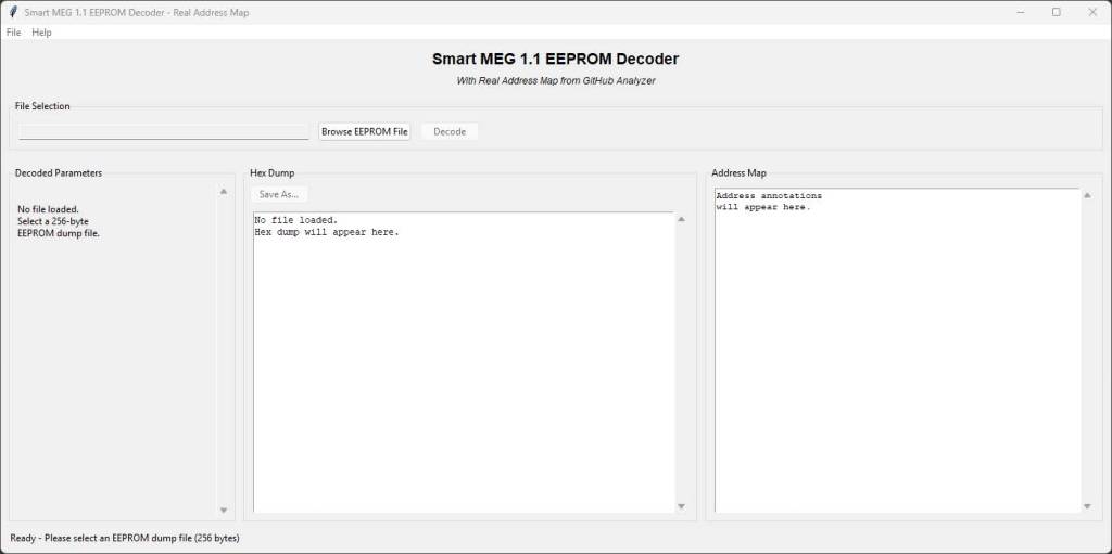
In my last post, I talked about how the MEG 1.1 EEPROM stores critical information like VIN numbers, engine models, immobilizer programming, and SCN coding that determines which maps the ECU uses.
What I didn’t mention is how difficult it’s been to actually see and understand all this data properly. Sure, you can read the EEPROM with the right tools, but interpreting those 256 bytes of hex data? That’s where things get tricky.
The Problem with Existing Tools
Most of the EEPROM analysis tools floating around the Smart community are incomplete fragments – usually old PHP scripts from forums that only decode bits and pieces. You might see the VIN, maybe some basic immobilizer data, but huge chunks of the EEPROM remain mysterious.
This became a real problem for me. When diagnosing ECU issues, swapping units between cars, or understanding why a particular remap wasn’t working properly, I needed to see everything stored in that little 24C02 chip.
I have also tried to avoid spending large sums of money on proprietary or cracked software which still may only give me part of the answers.
What’s Actually Stored in There?
After months of reverse engineering work (with plenty of help from the usual suspects – you know who you are!), I’ve mapped out most of the MEG 1.1 EEPROM structure. Here’s what Smart is actually storing in those 256 bytes:
Vehicle Identity & Configuration
- 0x35-0x37: Model code (452 = Roadster, 450 = Fortwo)
- 0x38-0x3A: Engine variant (434 = 61kw, 437 = 74kw Brabus, etc.)
- 0x3B: Steering configuration (LHD/RHD)
- 0x32-0x42: Complete VIN storage
- 0x0A-0x19: SCN ID code
The SCN Coding Mystery Solved (Partially!)
Remember how I mentioned SCN coding determines which maps the ECU uses? The actual coding lives at 0x05-0x06 and it’s far more detailed than anyone realized.
These two bytes contain 16 individual bits that control everything. I’ve managed to identify what some of them do:
- SCN5 Bit 6: Climate control presence
- SCN5 Bit 7: SB2 upgrade flag (the magic bit for Brabus maps!)
- SCN5 Bit 8: Roadster vs Fortwo identification
- SCN6 Bit 4: 45kW variant
- SCN6 Bit 5: 61kW variant
- SCN6 Bit 7: 74kW Brabus variant
But here’s the thing – many of the SCN control bits are still unknown. There are bits that clearly do something (they change between different ECU configurations), but I haven’t been able to figure out what they control yet.
This explains exactly how the ECU knows which internal maps to reference from the same FLASH file, but there’s clearly more functionality hidden in those unknown bits.
Immobilizer & Security Data
- 0x52: Key counter (immobilizer status)
- 0x2A-0x30: 7-byte immobilizer coding sequence
- 0xB4-0xB7: Immobilizer data blocks
- 0xA4-0xA5: Key programming data
Engine Management & Adaptations
- 0x5B: MIL status (check engine light)
- 0x5E-0x5F: Knock sensor reference values
- 0xA0-0xA1: Lambda sensor zero point
- 0x6C-0x6D: Odometer reading
Clutch & Gearbox Learning
- 0x9A-0x9B: Clutch protection class 1
- 0x9C-0x9D: Clutch protection class 2
- 0x9E-0x9F: Clutch protection class 3
- 0xA2-0xA3: Time spent in clutch protection mode
- 0xA6-0xA7: Clutch slip point learning
- 0xB0-0xB1: Disengaged position values
ECU History & Diagnostics
- 0xF2: Flash write counter (how many times it’s been remapped)
- 0xED: Flash type indicator (original sC vs tuning files)
- 0xE2-0xEC: Error byte range
- 0xF0-0xF1: Flash CRC verification
Building the Complete Decoder
Rather than keeping this knowledge locked away, I’ve built a proper Python tool with a clean GUI that decodes every single byte. This tool is provided here for free and I appreciate it if anyone who shows any use from this or has any input about what it does to please get in touch.
The SB2 Connection
Remember how I explained that SB2 maps have built-in protection? Now we can see exactly how it works. The ECU checks SCN5 Bit 7 to see if SB2 has been applied. If the FLASH contains SB2 maps but this bit isn’t set, limp mode kicks in within minutes.
This is why proper SCN coding (not just map flashing) is essential for SB2 conversions. The EEPROM and FLASH must match, or the protection system activates.
Update, I have successfully managed to make a modified SB2 map file which incorporates all the SB2 changes to the 371568 original map. This is the newest map file that Smart released and the only one which has faster gear changes. Please message me if you want a copy, all I ask is a donation for my time.
Still Much to Learn
Despite mapping out the complete EEPROM structure, there’s still a lot we don’t understand about these MEG 1.1 ECUs. The reverse engineering work has been like peeling back layers of an onion – every answer reveals new questions.
Some areas that need more investigation:
- Unknown SCN control bits – several bits change between configurations but their function is still mystery
- Adaptation algorithms – how exactly does the ECU learn and store clutch behavior?
- Inter-module communication – how does the MEG talk to the SAM and other modules?
- Hidden diagnostic functions – what other capabilities are buried in the firmware?
If anyone in the Smart community has additional knowledge about MEG 1.1 internals, SCN coding functions, or has discovered other interesting behaviors, please get in touch!
The more we understand these ECUs collectively, the better we can maintain, diagnose, and improve our cars. I’m always keen to collaborate and share knowledge with fellow Smart enthusiasts who are pushing the boundaries of what’s possible.
Looking Forward
More technical posts coming soon, including some exciting developments in gearbox control that build on this EEPROM knowledge…
Big thanks again to Mike Bailey at 223D Developmental and Andrew at Smart Automotive for their ongoing collaboration and pushing the boundaries of what’s possible with these brilliant little engines.
EEprom Decoder:
https://drive.google.com/file/d/1KGevWu-_O8_Ib1LeLYanKZSAPyb6HMDQ/view?usp=sharingTom
South Australia
WhatsApp: +61 401 723 903 -
Trials and Tribulations of Smart ECU Mapping
So you want more power from your Roadster eh?
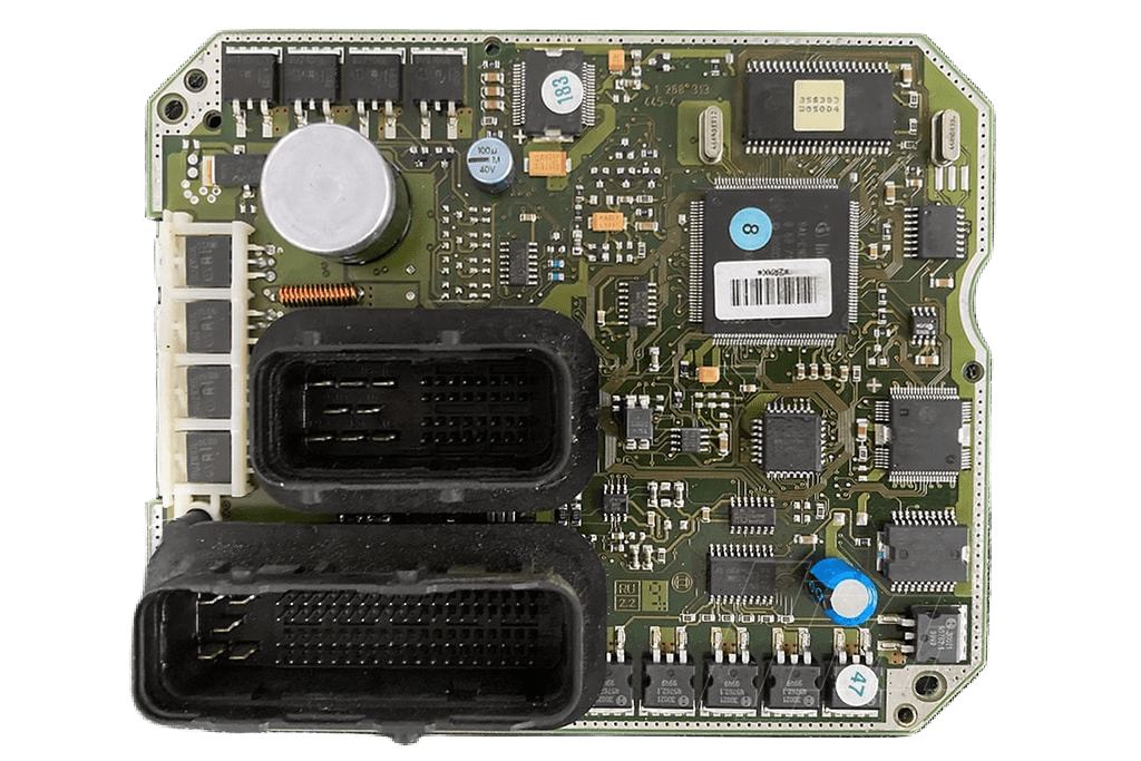
Smart Roadsters use a Bosch MEG1.1 ECU unit.
M stands for “Bosch Motronic” which can be traced back to Bosch’s first ECUs back in the 80s
E stands for “electronic accelerator” all Smart ECUs use drive-by-wire throttles where the accelerator pedal isn’t actually physically connected to the throttle body.
G stands for “Gearbox Control” all 450 Fortwo and Roadsters have the gearbox controlled by the ECU itself.
Unlike other Bosch ECUs like the ME7.5, the MEG1.1 in the Roadster has not had much reverse engineering done to it because the Roadster (and 450 Fortwo) are the only models which use this ECU.
Roadsters and 700cc Fortwos share the same MEG1.1 ECU and can be exchanged between the two with a bit of knowledge.
The MEG has two areas inside that can store information, the EEPROM and FLASH.
The EEPROM stores information about the car such as VIN number, engine model, immobilizer key programming, clutch grab point, gearbox learning adaptations and what options are enabled such as weather the Brabus tuning SB2 map has been applied or not.
The FLASH storage is a bigger chip that stores the “firmware” or the part that actually runs the engine and gearbox, this is where all the tables for how much fuel to put in, how much timing and how much boost to run.
When someone “remaps” the ecu, this is the chip that gets overwritten. EEPROM on the other hand is difficult to edit, usually requires removing the ECU from the car, opening it up and removing the entire chip off the board just to read and reflash it.
When someone “clones” an MEG, SAM or cluster, this is what they are doing; removing, reading and cloning the data on the internal EEPROM chips.
45kw Roadster Lite and 61kw regular Roadsters use the same map file, there are multiple maps inside the FLASH and the EEPROM tells it which maps to use.
Over the life of the roadster, there were 5 different revisions or versions for the 45/61kw that got released:
- 1037365163
- 1037365186
- 1037365239
- 1037365463
- 1037371568
Most of the changes between the versions are just small tweaks here and there to things like cold start, clutch engagement and emissions.
371568 is the biggest change of the lot, this is the one that got released in 2006? and was made after complaints that the gear changes were slow. This version has many tweaks to the gearbox control, driving it you can definitely notice the difference and gear changes are both faster and smoother.
Brabus Roadster (74kw and SB2) does have their own unique map files and there was only ever one version of each released. What this means that when the 371568 updated 61kw version got released, the Brabus models missed out on quicker and smoother gear changes.
The SB2 map, like all the maps have built in protection, you cant just load it using a flash tool to the ECU like other map files as the car will go into limp mode within a few minutes. The way this works is inside the EEPROM is an area that mentions if the car has had the SB2 map applied or not.
If the ECU starts and isn’t a model with the SB2 map applied but has the SB2 map loaded onto the FLASH then it goes into some sort of protection mode (limp mode) within a few minutes.
This is the same with 45/61kw variations, they use the same map but inside the EEPROM it states which variant it is and which internal values to reference.
The way the Smart dealers apply the SB2 map is with the STAR diagnostics unit, it updates both the FLASH and EEPROM to both be SB2.
Most people (who aren’t Mercedes) use STAR systems that aren’t genuine or legal. The way these work is mainly offline (no connection to Mercedes servers). To be able to use the SB2 map, the EEPROM needs to be edited to match the map file and this is called SCN coding on the STAR units.
Offline SCN coding is rare and not many people have the ability to do this. This means that loading the Brabus SB2 map via a STAR diagnostics unit is extremely rare outside of Mercedes.
Most generic “remappers” out there (who aren’t Smart specialists) who say they can reflash your Roadsters if you bring in your car will load a tune which they themselves have probably found online from an illegal leaked database.
These databases are the same ones which can be bought on eBay for a very small amount of money. They are the same bunch of files from pretty much every seller.
Only tuners which are smart specialists or have a dyno and have developed their own tune are to be relied upon.
Big thanks to Mike Bailey at 223D Developmental who has helped (and pushed) me to discover more along with Andrew at Smart Automotive who has also collaborated on this journey.
More posts to follow…
-
Wow I forgot this page existed!

Lots has changed since I started this website!
In my spare time (when I’m not at my day job) You’ll find me tinkering on my (many) smart roadsters or customers cars.
I have developed with the help from Mike Bailey at 223D Developmental A remap which truly unlocks the power hiding within these engines.
The biggest flaw of these vehicles is the gearbox, and many agree that it leaves much more to be desired. What if I told you that we have managed to speed up the gear changes to the point where this isn’t an issue anymore?
If you’re interested in hearing more, I will make some posts detailing the process and what’s required.
This is a quick post to say that I’m well and truly still devoted to these vehicles and that there is more to come!
Please get in touch with me on Facebook, or Whatsapp (+61 401 723 903)
-
Hello Roadster Fans!
Welcome to my new site!
Over the course of a few years I have gained extensive knowledge of Smart Roadsters and how to work on them.
The purpose of this site is to share what I have found and try to make obtaining information easier for Roadster & Fortwo owners alike.
Who am I? I’m Tom from South Australia and currently own 2 61kw Smart roadsters (no Brabus models in Aus) & one 600cc Fortwo.
My background is in small turbocharged engined cars, mainly Japanese Daihatsus of which I own a Mira Gino L700 model.
-
Subscribe
Subscribed
Have a WordPress.com account? Log in now.

